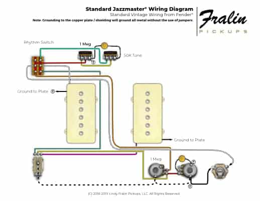
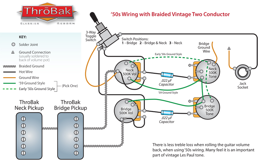
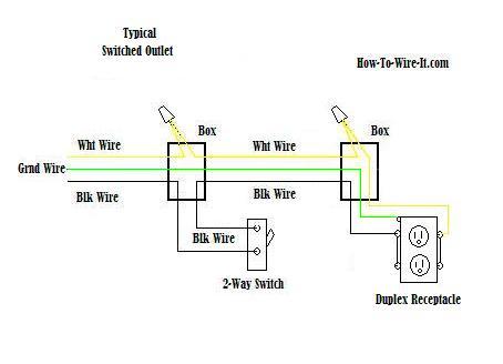
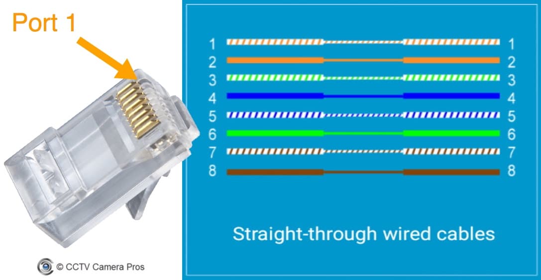
This is why a good diagram is important for wiring your home accurately and according to electrical codes. The hot and neutral terminals on each fixture are spliced with a pigtail to the circuit wires which then continue on to the next light.
To connect the electric system of your trailer to the vehicle you will be using special connector.

You can find out more Diagram below
Wired diagram. 4 pin trailer wiring diagram. A wiring diagram is a simplified conventional pictorial representation of an electrical circuit. This diagram illustrates wiring for one switch to control 2 or more lights.
A wiring diagram is a simple visual representation of the physical connections and physical layout of an electrical system or circuit. Typical trailer wiring diagram and schematic. The image above shows a single axle trailer and the next image shows wiring for tandem axles.
Multiple light wiring diagram. Above we have describes the main types of trailer wiring diagrams. Wiring diagrams this is not an automated service.
As this is a free service it receives an overwhelming amount of requests and may take up to a week or longer for a response. This is the simplest arrangement. It shows the components of the circuit as simplified shapes and the power and signal connections between the devices.
Each diagram that is requested has to be hand selected and sent. The source is at sw1 and 2 wire cable runs from there to the fixtures. Only the blue brake and white ground wires are different.
These 2 wire diagrams fit the needs for most trailers. It shows how the electrical wires are interconnected and can also show where fixtures and components may be connected to the system. Wiring diagrams can be helpful in many ways including illustrated wire colors showing where different elements of your project go using electrical symbols and showing what wire goes where.
Below is the generic schematic of how the wiring goes. Extrapolate the same expansion for additional axles.


0 comments:
Post a Comment