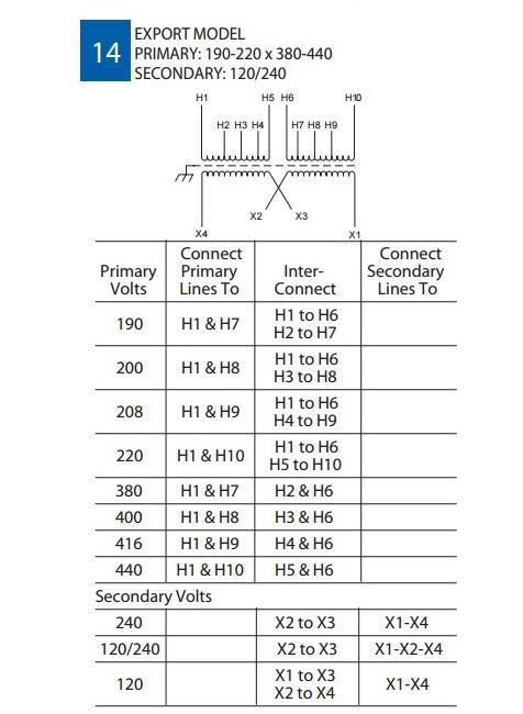
The low voltage side terminals are marked similarly using x instead of h. When the transformer windings are drawn a particular high voltage winding corresponds to the low voltage winding drawn parallel to it.
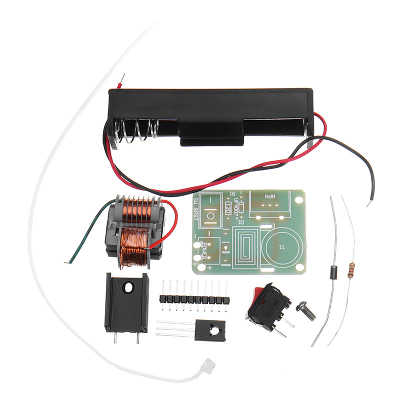
A simple 14 va mains transformer and a discrete voltage multiplier.

You can find out more Diagram below
High voltage transformer wiring diagram. High voltage substation design diagrams. A generator is a core component of many peoples emergency preparedness plans. A three phase transformer is built for a specific connection and voltage transformation and the unit will have a nameplate with the internal connections shown.
In other words a high voltage winding and a low voltage winding that are drawn parallel to each other constitute a single phase transformer or two windings on the same leg of the magnetic core of a three phase. Its also important to understand relationship between protection and the other equipment in the substations and the distribution system. A substation engineer should have a good understanding of the electrical equipment and layout of hv power substation.
It is used when both single and three phase power is desired to be supplied from a three phase transformer or transformer bank. High voltage wiring diagram here you are at our site this is images about high voltage wiring diagram posted by brenda botha in high category on oct 23 2019. In most cases pts are used with medium voltage circuits ranging from 2400 vac to 35000 vac so this will show medium voltage examples.
High voltage generator schematic circuit diagram. Pt and ct secondary neutrals shall be on separate conductors and run from the metering transformers to the meter. The same circuits may also be used for lower or high voltage pts.
P1 is used to set the maximum current and p2 sets the output voltage. Maybe you have a. You can also find other images like images wiring diagram images parts diagram images replacement parts images electrical diagram images repair manuals images engine diagram images engine scheme diagram images wiring harness.
Transformers for high voltage operation with the star connections has the advantage of reducing the voltage on an individual transformer reducing the number of turns required and an increase in the size of the conductors making the coil windings easier and cheaper to insulate than delta transformers. Generator wiring diagram and electrical schematics. The pt secondary neutral conductor is white with green stripes wgs and the ct secondary neutral conductor is solid white.
Electric revenue highvoltage metering 063436 page 2 of 14 rev. It provides recommended wiring diagrams and information on the measurements. High leg delta also known as wild leg stinger leg bastard leg high leg orange leg or red leg delta is a type of electrical service connection for three phase electric power installations.
For the three phase transformer the high voltage phase terminals are designated by the letter h.


0 comments:
Post a Comment