Thermostat wiring diagrams white rodgers shows a slightly different type of wiring diagram that mirrors a ladder logic diagram. There are three basic types of wiring diagrams used in the hvacr industry today.
The first and most common is the ladder diagram.

You can find out more Diagram below
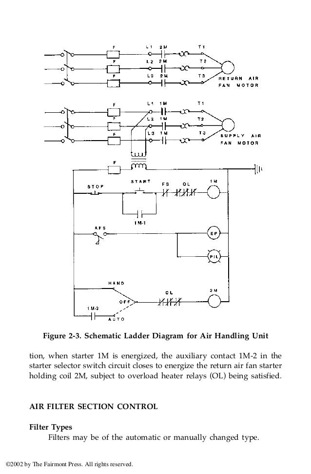
Hvac ladder wiring diagram. It is called ladder because the symbols that are used to represent the components in the system have been placed on the rungs of a ladder. Some of these can appear complicated but they are usually very simple when you start at the beginning and wind up at the end. After explaining basic ladder diagrams and showing several examples ask the students to draw a simple diagram of a packages air conditioning unit without looking at an example.
The first and most common is the ladder diagram so called because it looks like the symbols that are used to represent the components in the system have been placed on the rungs of a ladder. From this point forward ladder dia. It is clear and understandable.
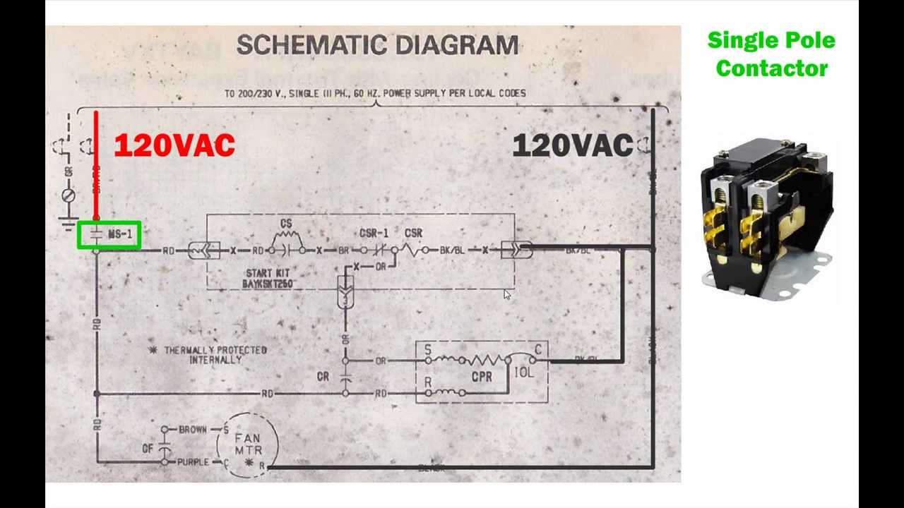
Electrical wiring diagrams for air conditioning systems part one in article electrical rules and calculations for air conditioning systems. B legend factory power wiring factory control wiring field control wiring field power wiring component connection field splice junction contactor capacitor dual run crankcase heater. Connection diagram g 13 equip gnd l1 11 21 ch comp cont 23 ofm cap l3 schematic diagram ladder form may be factory or field installed 319390 401 rev.
I have to include compressor running capacitor compressor safety thermostat thermostat terminal board transformer thermostat reversing valve solenoid outdoor fan motor capacitor outdoor fan motor high pressure switch low pressure switch indoor fan. In a ladder diagram all the related components or subcomponents are. Electrical schematics are used to make it simple to trace the circuits of various devices.
I have to make a ladder diagram of a heat pump package air conditioning system. I am taking a course and have an assignment. From this point forward ladder diagrams will be referred to as schematic diagrams or schematics the second type of diagram is the line diagram.
It is the most common type of wiring diagrams. Types of wiring diagrams there are three basic types of wiring diagrams used in the hvacr industrytoday. The ladder diagram is the wiring diagram of choice because it makes it easier to see how the various components are related.
At least to an expert. Just know that there is no use trying to explain a ladder diagram that contains 24 volt control relays to someone that does not understand how relays work. This diagram shows what each terminal designation that goes to the hvac system.


0 comments:
Post a Comment